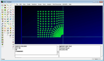
This page describes the basic operation of the M3d pre and post Processor. To load this M3d demonstration Finite Element model:-
1) Unzip the downloaded package to a suitable location;
2) Double click the M3da.exe application file to start M3d and
3) From the File menu select File->Import->DAT and select the PlateHole.dat file supplied with the package.
The model shown right should be displayed in the M3d modellers' main window.
The Interface
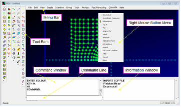
Right is a picture of the M3d main screen with the main interface elements labeled. M3d commands can be accessed by the Menu Bar or Icon Tool Bars. Commands may also be typed on the command line and this can be used for basic scripting. On invoking a command the command window will prompt you for the necessary information. Information messages are written to the information window.
Common options which can be used with the commands are available from the right mouse button menu
Dynamic Viewing
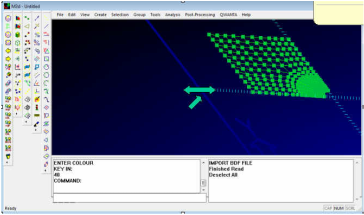
Panning The model may be translated by holding the F1 (alternatively the ctrl) key and moving the mouse in the viewing area.
Zooming The model may be zoomed in and out by holding the F2 key and moving the mouse up and down in the viewing area, alternatively the mouse roller button can be used.
Rotation The model may be rotated by holding the F3 (alternatively the shift) key and moving the mouse in the viewing area

Set Rotation Centre
This allows you to pick a location from the model to rotate the model around and also centres the view at that location.
This allows you to pick a location from the model to rotate the model around and also centres the view at that location.

Resets view to global
Selection
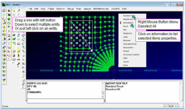
All entities (nodes, element, curves, surfaces etc) are selectable in M3d by clicking on them with the left mouse button or dragging a box over them with the left button down. Once selected they will appear highlighted as shown in the picture right. Clicking on them again deselects them. To deselect all items right click the mouse button to bring up the menu and select 'Deselect All' menu item.
To get information on selected items, like node coordinates, from the right mouse button menu click on 'Information'. Information will be listed in the information window.
Note double clicking on an item will select the parent entity. For instance double click a node will select it's parent mesh.
Selection Filter
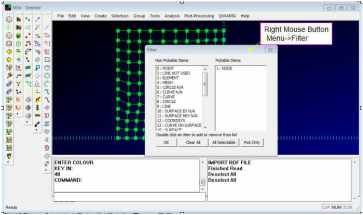
To make it easier to select only items of a certain type from the right mouse menu pick the 'Filter Menu' option. This brings up the Filter dialog box which lets you decide what items are selectable. In the picture right the filter is set to select only nodes. The filter will stay set until you change it again. So if for some reason you are having problems selecting items, check the filter settings.
Note also some commands automatically change the filter and may not set it back to the default settings.
Related To
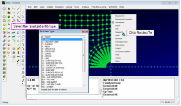
This feature helps you select items related to other items. For instance you may want to select all the nodes related to some selected elements or vice versa.
As an example, first select a few elements from the screen by clicking on them. Now from the right mouse menu select the 'Related To' option, this will bring up a dialog. Select the resultant entity type node. Now accept the selection or pick more elements. When done click the middle mouse button to accept the selection. Now all the nodes on the selected elements should be highlighted.
This command can be chained together for instance to select elements related to nodes related to elements.
Command Behaviour
Most commands when invoked from either the tool bars, menus or command line, prompt you for information in the command window. The command may require you to:- enter coordinates; pick items from the screen or ask for other information.
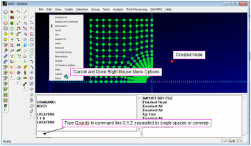
To cancel out of a command at any time you can press the escape key or select 'Cancel' from the right mouse button menu. To commit to a command press the enter key or select 'Done' from the right mouse button menu.
Example Creating Nodes
In the command line type 'NCR' this activates the node create command. You will be prompted to enter a coordinate. In the command line type '1,1,0' and press enter. A node should be created on the screen. You can carry on typing in coordinates until you exit the command by pressing the escape key or selecting 'Cancel' from the right mouse button menu.

This icon also starts the node create command.
Translation Options
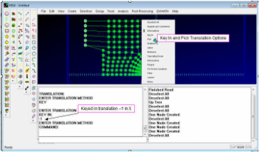
Many of the commands require you to enter a vector for instance to move something by. There are two methods for doing this; one is to type in the vector (e.g. -10,3,2) the other is to pick two locations from the screen (e.g. two different nodes). Under the right mouse button we have the two options 'Key In' and 'Pick'. When in a command and prompted for 'ENTER TRANSLATION METHOD' select one of the two options by either typing 'Key' or 'Pick' on the command line or from the right mouse button menu.
Example Moving Nodes
It's a good idea before starting this command to do a 'Deselect All' by selecting 'Deselect All' from the right mouse button menu (just in case some unwanted nodes are already selected).
In the command line type 'MOVE' to start the move command. You will then be prompted to pick some items to move. Pick some nodes from the model as shown right. When selected, press the middle mouse button or select 'Done' from right mouse button menu. You will then be prompted to 'ENTER THE TRANSLATION METHOD'. From the right mouse button menu select 'Key In' or 'Pick'. In the case of 'Key In' type in a translation vector on the command line (e.g. -1,0.2,0) or if the option was 'Pick' select two locations from the screen (e.g. two different nodes to define the translation vector).

This icon also starts the move command.
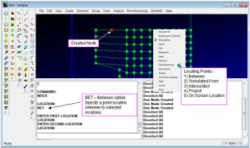
Location Acquisition
This relates to specifying a point location in the model. Many commands ask you to specify a location and you do this by picking an item from the screen. These location acquisition functions help you define a location.
The options available from the right mouse button menu are:-
1) 'Between' - this gives you a point between two other points;
2) 'Translated From' - this gives you a point translated away from another specified location;
3) 'Intersection' - this gives you the location at the intersection of two selected lines or curves;
4) 'Project' - this gives you a point at the projected location of another selected point onto a line or surface and
5) 'On Screen Location' allows you to pick a location on the screen projected to the work plain.
Most of these commands can be chained together, for instance to give you a point translated from a point between two other points.
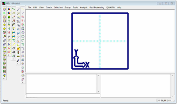
The Workplain
The workplain is show in the picture right. Its default size is 10x10 square in X & Y with 0,0 at the centre.
When coordinates are entered they are relative to the workplain. The workplain can be moved to any other location or into another orientation to aid modelling. The workplain can also be switched to polor coordinate mode so points can be entered in R, Theta, Z ordinates.
The workplain tools are under the menu Tools->Workplain.

Display Selected
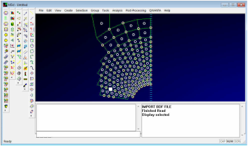
This allows you to display just the selected entities in a temporary group. This is invaluable when working with large models. Select the items you want to display then click the 'Display Selected' icon shown above. Only the selected items will then be displayed on the screen. Then do 'Deselect All' and carry on working.

Display All
To display the whole model again press the 'Display All' icon shown above.
To display the whole model again press the 'Display All' icon shown above.