This page describes the newly added 2d surface meshing capability added to M3d. This a free meshing algorithm which can tri mesh surfaces of any arbitrary domain and is based on the Advancing Front technique.
The 2d surface mesh generator at present is limited to 2d planar surface created in M3d using the surface by boundary command ("SURBOUND"). The functionality will be extended to any surface type.
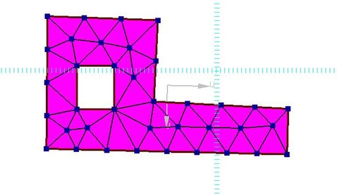
An example of a mesh generated on a trimmed surface with an internal trim loop is shown below:-
The 2d surface mesh generator at present is limited to 2d planar surface created in M3d using the surface by boundary command ("SURBOUND"). The functionality will be extended to any surface type.
An example of a mesh generated on a trimmed surface with an internal trim loop is shown below:-
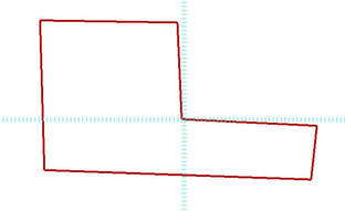
1) Create a 2d enclosed curve boundary in the X-Y plane using the 2d wireframe drawing tools. Note the plane can actually be in any orientation as long as it is a planar surface (for now). In this example we are using the X-Y plane so the section properties function can be demonstrated. The section properties function is limited to surface in the X-Y plane so moments of area can be calculated for Ixx and Iyy.

Any of the wire-frame drawing tools can be used to create an enclosed boundary. In this example the continuous line function was used (command "LNC") . This connects sequential selected points until the command is canceled. Points can be entered on the command line or located by clicking a location in the X-Y plane from the screen.
An example on an enclosed boundary is shown below:-
An example on an enclosed boundary is shown below:-
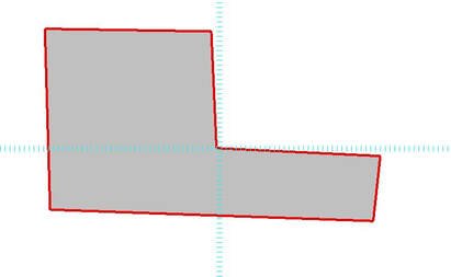
2) Create the surface from the wire-frame boundary
Click the surface by boundary icon or type "SURBOUND" in the command line. You are then prompted to pick the curves forming the boundary. Pick the curves from the screen, these can be picked individually or you can drag a selection box over them all. Note: only the curves that form a complete boundary must picked - no extra's. Then press enter or select "Done" from the right mouse menu.
If you find that you can not pick the curves from the screen check the selection Filter to ensure curves are selectable. The filter is accessible from the right mouse menu option "Filter".
Select the shaded view option to check a valid surface has been created as illustrated below:-
From the right mouse menu select option "Deselect All" to ensure nothing is in the selection buffer.
3) Create any internal trim loops, if any, these are regions that form holes in the surface.
3) Create any internal trim loops, if any, these are regions that form holes in the surface.
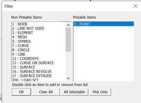
- From the right mouse menu select "Filter" which will show the filter dialog box. Make "Point" the only selectable item type, by picking point from the list and pressing the "Pick Only" button. This ensures for subsequent commands only point locations are pickable from the screen.

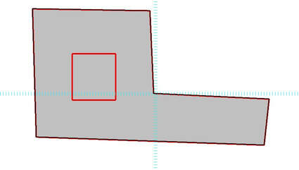
Select the rectangle icon or type "RECT" in the command line and pick two point from the screen to create a rectangle within the created surface boundary. The upper right corner must be picked first and than the lower left.
The resulting rectangle that will form the internal rim loop is shown below:-
The resulting rectangle that will form the internal rim loop is shown below:-

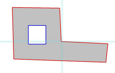
Click the surface internal trim loop icon or enter command "SURTRIMLOOP" then pick the surface and the 4 curve forming the internal loop and press enter or "Done" from the right mouse menu.
The resulting surface is shown below:-
The resulting surface is shown below:-
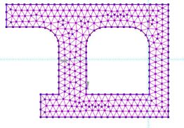
4) Create the 2d mesh on the surface.

Select the 2d tri mesh icon or command "MMESHAF" pick the surface from the screen and then enter the required element size in the command line. The resulting mesh is shown below:-